What Is Rung In A Ladder Logic Diagram. Ladder logic consists of horizontal rungs and instructions embedded. It has two vertical line, which is called as rails, the left rail supplies power to the circuit, then it passes through each rung. a ladder diagram is the symbolic representation of the control logic used for programming of a plc. ladder logic is a visual programming language used to program plc’s (programmable logic controllers). ladder logic diagram are graphical programming language which executes through real time input. each rung of the ladder spans from left to right and is executed from top to bottom by the plc. these diagrams documented how connections between devices were made on relay panels; They are called “ladder” diagrams because they are constructed in a way that resembles a ladder with two vertical rails and rungs between them. horizontal lines in a ladder diagram are called “rungs,” each one representing a unique parallel circuit branch between the poles of the power supply. Each rung has switches and output coil. As mentioned above, ladder logic is extremely popular among.
from www.youtube.com
a ladder diagram is the symbolic representation of the control logic used for programming of a plc. They are called “ladder” diagrams because they are constructed in a way that resembles a ladder with two vertical rails and rungs between them. ladder logic is a visual programming language used to program plc’s (programmable logic controllers). each rung of the ladder spans from left to right and is executed from top to bottom by the plc. Each rung has switches and output coil. Ladder logic consists of horizontal rungs and instructions embedded. horizontal lines in a ladder diagram are called “rungs,” each one representing a unique parallel circuit branch between the poles of the power supply. As mentioned above, ladder logic is extremely popular among. these diagrams documented how connections between devices were made on relay panels; ladder logic diagram are graphical programming language which executes through real time input.
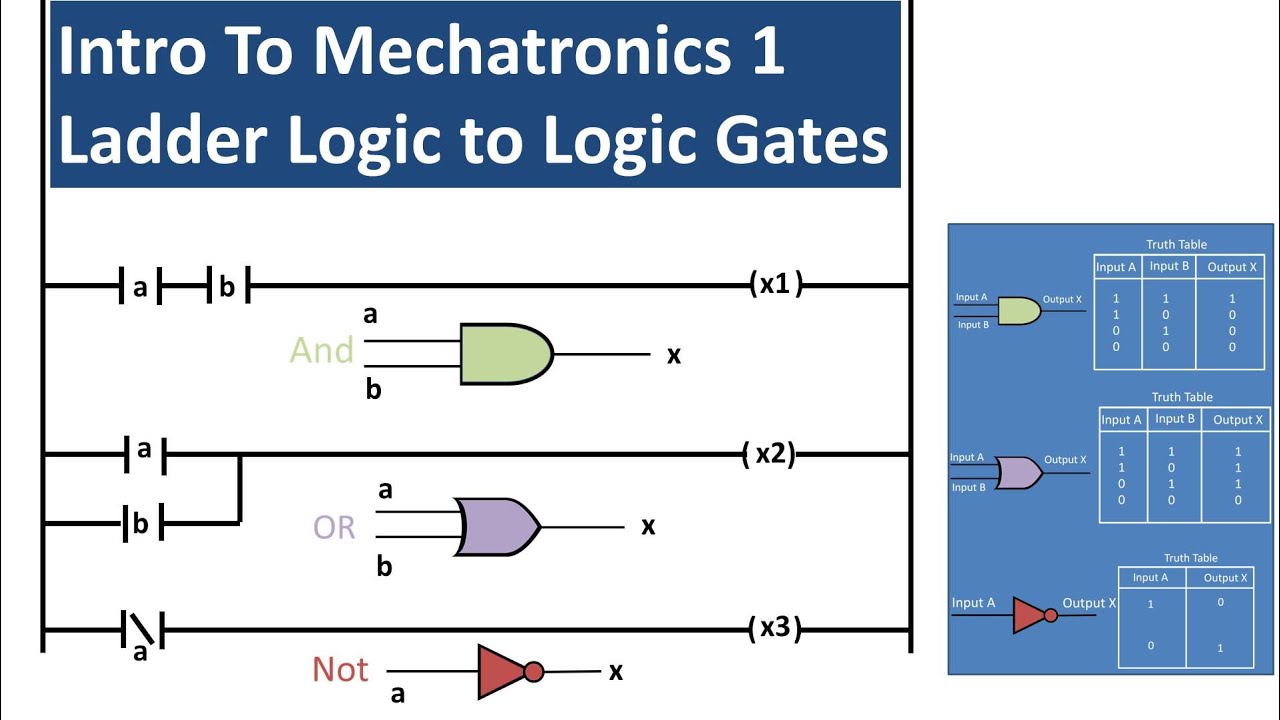
Basics of Ladder Logic and Logic Gate Equivalents (Mechatronics 1
What Is Rung In A Ladder Logic Diagram It has two vertical line, which is called as rails, the left rail supplies power to the circuit, then it passes through each rung. ladder logic is a visual programming language used to program plc’s (programmable logic controllers). ladder logic diagram are graphical programming language which executes through real time input. It has two vertical line, which is called as rails, the left rail supplies power to the circuit, then it passes through each rung. Ladder logic consists of horizontal rungs and instructions embedded. horizontal lines in a ladder diagram are called “rungs,” each one representing a unique parallel circuit branch between the poles of the power supply. They are called “ladder” diagrams because they are constructed in a way that resembles a ladder with two vertical rails and rungs between them. As mentioned above, ladder logic is extremely popular among. Each rung has switches and output coil. each rung of the ladder spans from left to right and is executed from top to bottom by the plc. a ladder diagram is the symbolic representation of the control logic used for programming of a plc. these diagrams documented how connections between devices were made on relay panels;